LED blinking using PIC16F877A and MikroC
In this Tutorial we will learn how to blinking LED use PIC Microcontroller. Here I am use PIC16F877A Microcontroller and MikroC compiler.
You can watch the flowing video tutorial and read the written bellow.
PIC16F877A Microcontroller has A0-A7, B0-B7, C0-C7, D0-D7 and E0-E2 input/output port. Some pins for these I/O port are multiplex with an alternative function for the peripheral feature on the device. In general, when a peripheral is enable, that pin may not used as a general purpose I/O pin.
PORTB Register
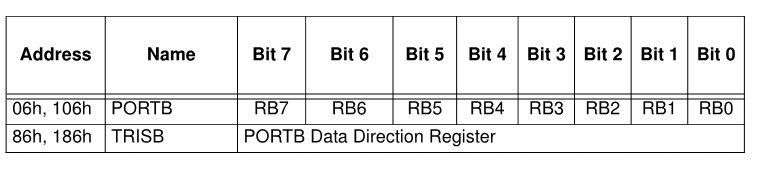
The TRIS Register controls the direction of Input/Output port. Here PORTB is 8bit wide, bi-directional port. The corresponding data direction register is TRISB. Setting a TRISB bit (= 1) will make the corresponding PORTB pin an Input. Clearing a TRISB bit (=0) will make the corresponding PORTB pin an Output.
Circuit diagram:

Component needed for this Project
- PIC16F877A Microcontroller
- 8MHz Quartz Crystal
- Push button
- LED 5mm
- Resister: 10k ,1k
- Breadboard
- Jumper Wire
- 5V DC Supplay
MikroC Project Code
void main(){
TRISB0_bit = 0; // RB0 pin is output
PORTB = 0; // PORTB is clear
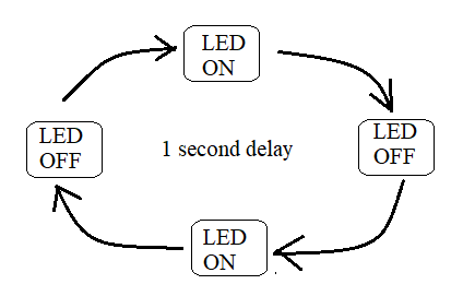
while(1) { // endless loop
RB0_bit = 1; // RB0 is high
delay_ms(1000); // 1second delay
RB0_bit = 0; // RB1 is low
delay_ms(1000); // 1second delay
}
}
Code Explain:
Here I am use Mikro C compiler for code editing. In void main function I define RB0 pin is output by clearing TRISB register. Then we clear the PORTB register. In next, here I am use while loop for continues program execution. And then close the program.

Post Comments