How to make digital voltmeter use PIC16F877A Microcontroller and MikroC
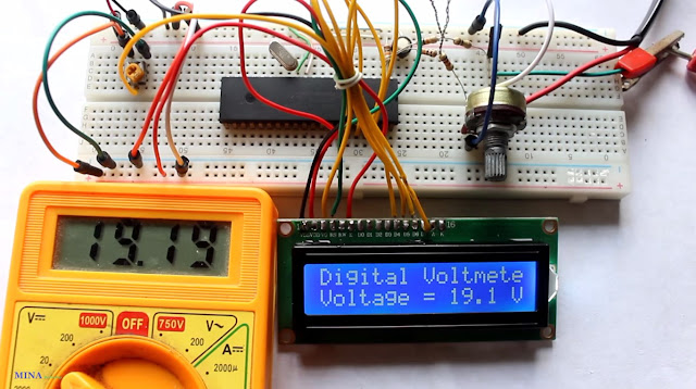
In this tutorial we will learn how to make a digital voltmeter use pic microntroller. Here I am use PIC16F877A and LM16x2 Lcd display. PIC16F877A microcontroller has 8 channel analog input. In this project I am analog channel 0 for analog to digital conversion. You can watch the video or read the written tutorial below.
PIC16F877A microcontroller has 8 channel ADC(Analog to Digital Converter) module. ADC module has software selectable high and low voltage reference input to some combination of VDD, VSS, RA2 and RA3. The ADC module recived analog signal and it convert 10 bit binary numbers. It can measure (0-5)V DC
PIC16F877A microcontroller can be measure 0 to 5V . If measure high voltage we need to voltage divider circuit. In this project we measure the voltage 0 to 30V.
Voltage Divider Circuit
- First of all let I discuss how do we measure voltage? Actually PIC’s ADC can measure 0V to +5V, but here our voltage range is 0V to +30V.
- Hence we can’t feed the input voltage directly to the controller’s ADC pins. Instead of feeding directly, input voltage is reduced by a combination of voltage divider resistors.
Maximum allowed drop will be 5V
Voltage Divider Circuit

5 = Vin(max)*R2/(R1+R2)

Here,
      Vin(max)=30V; and assume R2= 22k ;
       5 = 30 * 22K(R1+R2)
       R1+R2 = (30 * 22K)/5
                   = 132000
                   = 132 K

      R1 = 132 K - R2  = 132 K - 22K = 110K

Actual calculate input voltage from voltage divider circuit.
PIC Microcontroller read voltage across the 22K resistor. So calculate voltage across 22K resistor by the voltage divider rule.
assume V22 voltgae drop across 22K resistor.
V22 = (Vin/(110K+22K)) * 22K
V22 = (Vin/(132K) * 22K)

This V22 is read to microcontroller's ADC module
Hence,
           The actual input
            Vin = (V22*132) / 22K
             Vin = V22 * 6
Circuit schametic of Digital Voltmeter

Mapping ADC Values to Input Voltage
- PIC microcontroller ADC is a 10 bit ADC, that means the output of ADC can be vary from 0 to 1023 maximum while input varies from 0 to 5V.
- That is when the input voltage is +5V then ADC value is 1023, when input voltage is 0V ADC value will be 0.
- We have to map 0 → 1023 to 0 → 5; it can be done by multiplying ADC value with a constant K.
K= Maximum ADC Voltage / Maximum ADC Value
= 5 / 1023 = 4.89 * 10^-3 = 4.89m
Vactual = ADC Value * 4.89m * 6
For example let's say ADC Value is 1023
Vactual = 1023 * 4.89m * 6
= 30.014V.
Mikro C Pro For Pic provide a ADC library with comfortable working with the ADC module.
Project Code
// LCD module connections
sbit LCD_RS at RB0_bit;
sbit LCD_EN at RB1_bit;
sbit LCD_D4 at RB2_bit;
sbit LCD_D5 at RB3_bit;
sbit LCD_D6 at RB4_bit;
sbit LCD_D7 at RB5_bit;

sbit LCD_RS_Direction at TRISB0_bit;
sbit LCD_EN_Direction at TRISB1_bit;
sbit LCD_D4_Direction at TRISB2_bit;
sbit LCD_D5_Direction at TRISB3_bit;
sbit LCD_D6_Direction at TRISB4_bit;
sbit LCD_D7_Direction at TRISB5_bit;
// End LCD module connections

char look(int a)
{
  switch(a)
  {
    case 0:
      return '0';
    case 1:
      return '1';
    case 2:
      return '2';
    case 3:
      return '3';
    case 4:
      return '4';
    case 5:
      return '5';
    case 6:
      return '6';
    case 7:
      return '7';
    case 8:
      return '8';
    case 9:
      return '9';
    default:
      return '.';
  }
}

void main()
{
  unsigned int v;
  char *volt = "00.0";
  CMCON = 0x07;
  TRISA = 0xFF;                       // PORTA is Analog input
  PORTA = 0X00;                       // PORTA is clear
  ADCON1 = 0x00;
  Lcd_Init();                         // Initialize lcd module
  ADC_Init();                         // Initialize ADC module
  Lcd_Cmd(_LCD_CLEAR);                // Clear Lcd display
  Lcd_Cmd(_LCD_CURSOR_OFF);           // Cursor of the Lcd display
  Lcd_Out(1,1, "DEVELOPED BY");       // Lcd show "DEVELOPED BY"
  Lcd_Out(2,1, "MINA TECHNOLOGY");    // Lcd show "MINA TECHNOLOGY"
  delay_ms(2000);                     // 2 second delay
  Lcd_Cmd(_LCD_CLEAR);                // Clear Lcd display

  do                                  // loop start
  {
    v = ADC_Read(0);                  // RA0 is Analog input
    v = (v*4.89*6) ;                  // 4.89 is Resulation
    volt[0] = look(v/10000);
    volt[1] = look((v/1000)%10);
    volt[3] = look((v/100)%10);
    Lcd_Out(1,1,"Digital Voltmeter");
    Lcd_Out(2,1,"Voltage = ");
    Lcd_Out(2,11,volt);
    Lcd_Out(2,16,"V");

    Delay_ms(500) ;                   // 500ms delay

  } while(1);                         // loop end
}
Download free source code

Post Comments