Generate PWM signal using PIC16F877A microcontroller and MikroC
In this tutorial we will learn Pulse Width Modulation(PWM) technique in microcontroller. Pulse Width Modulation use for control the output voltage. You can watch the video or read the written tutorial below.
Pulse Width Modulation is the method to produce variable voltage and different duty cycle. PWM use for Led brightness control, DC motor speed control and generate different duty cycle frequency.

PIC16F877A microcontroller has two CCP(Capture / Compare / PWM) module.
- CCP1
- CCP2
Each Capture / Compare / PWM(CCP) module contains a 16 bit register which can operate as a:
- 16 bit Capture register
- 16 bit Compare register
- PWM Master / Slave Duty Cycle register.
Both the CCP1 and CCP2 module are identical in operation , whit the exception being the operation of the special even trigger.
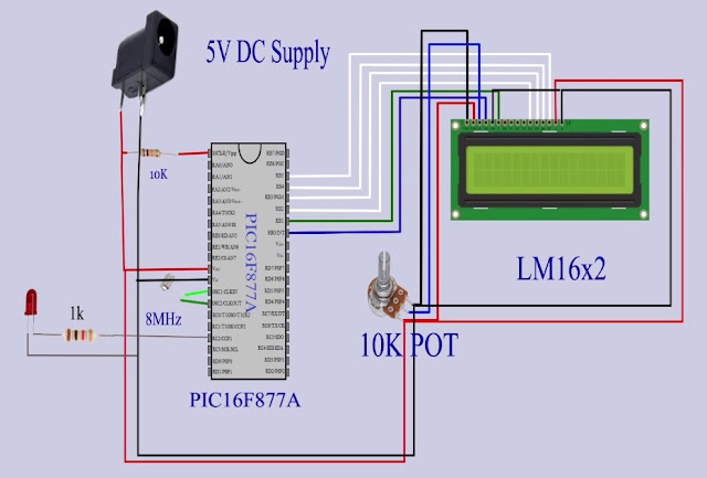
Circuit Schematic
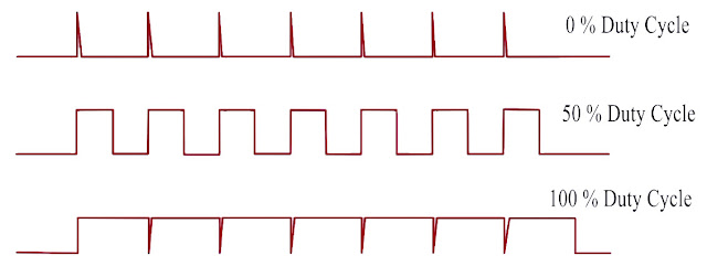
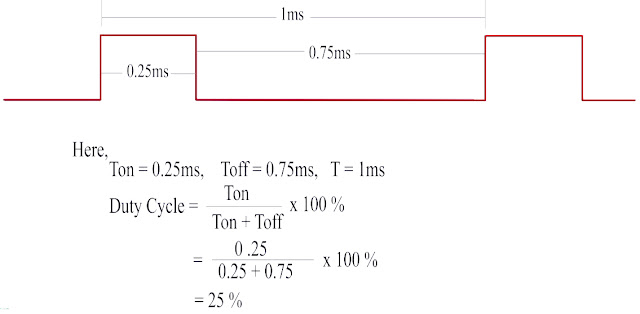
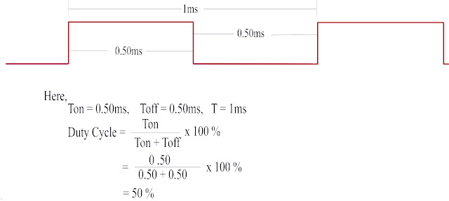
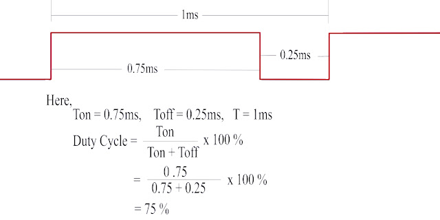
Different Type Duty Cycles
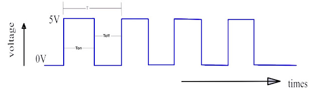
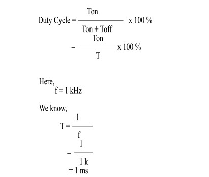

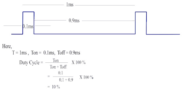
Relation Between Duty cycle and Output voltage
Output voltage = Duty cycle x Vout(max)

                                Here,
                                          Vout(max) = 5V


                                 assume,
                                               duty cycle = 25 %

                                                Ouput voltage = (25/100) x 5

                                                                        =  1.25 V

                                 assume,
                                               duty cycle = 50 %

                                                Ouput voltage = (50/100) x 5


                                                                        =  2.5 V


                                 assume,
                                               duty cycle = 75 %

                                                Ouput voltage = (75/100) x 5


                                                                        =  3.75 V


                                 assume,
                                               duty cycle = 100 %

                                                Ouput voltage = (100/100) x 5


                                                                        =  5 V
MikroC PRO for PIC provides a PWM Library which simplifies using PWM HW Module.
Project Code
unsigned int i;
// Lcd module connections
sbit LCD_RS at RB0_bit;
sbit LCD_EN at RB1_bit;
sbit LCD_D4 at RB2_bit;
sbit LCD_D5 at RB3_bit;
sbit LCD_D6 at RB4_bit;
sbit LCD_D7 at RB5_bit;

sbit LCD_RS_Direction at TRISB0_bit;
sbit LCD_EN_Direction at TRISB1_bit;
sbit LCD_D4_Direction at TRISB2_bit;
sbit LCD_D5_Direction at TRISB3_bit;
sbit LCD_D6_Direction at TRISB4_bit;
sbit LCD_D7_Direction at TRISB5_bit;
// End Lcd module connections
void main() {
     Lcd_Init();
     PWM1_Init(1000);
     PWM1_Start();
     Lcd_Cmd(_LCD_CLEAR);
     Lcd_Cmd(_LCD_CURSOR_OFF);
     Lcd_Out(1,1,"DEVELOPED BY");
     Lcd_Out(2,1,"MINA TECHNOLOGY");
     delay_ms(1000);
     Lcd_Cmd(_LCD_CLEAR);
     Lcd_Out(1,7,"PWM");
     Lcd_Out(2,1,"Duty Cycle:");
     Lcd_Out(2,15,"%");
     while(1){
              //duty cycle : duty ratio calculate (percent * 255) / 100
              // 0% duty cycle
              PWM1_Set_Duty(0);
              Lcd_Out(2,12,"  0");
              delay_ms(2000);

              // 10% duty cycle
              PWM1_Set_Duty(25.5);
              Lcd_Out(2,12," 10");
              delay_ms(2000);

              // 20% duty cycle
              PWM1_Set_Duty(51);
              Lcd_Out(2,12," 20");
              delay_ms(2000);

              // 30% duty cycle
              PWM1_Set_Duty(76.5);
              Lcd_Out(2,12," 30");
              delay_ms(2000);

              // 40% duty cycle
              PWM1_Set_Duty(102);
              Lcd_Out(2,12," 40");
              delay_ms(2000);

              // 50% duty cycle
              PWM1_Set_Duty(127);
              Lcd_Out(2,12," 50");
              delay_ms(2000);

              // 60% duty cycle
              PWM1_Set_Duty(153);
              Lcd_Out(2,12," 60");
              delay_ms(2000);

              // 70% duty cycle
              PWM1_Set_Duty(178.5);
              Lcd_Out(2,12," 70");
              delay_ms(2000);

              // 80% duty cycle
              PWM1_Set_Duty(204);
              Lcd_Out(2,12," 80");
              delay_ms(2000);

              // 90% duty cycle
              PWM1_Set_Duty(229.5);
              Lcd_Out(2,12," 90");
              delay_ms(2000);

              // 100% duty cycle
              PWM1_Set_Duty(255);
              Lcd_Out(2,12,"100");
              delay_ms(2000);

              // 90% duty cycle
              PWM1_Set_Duty(229.5);
              Lcd_Out(2,12," 90");
              delay_ms(2000);

              // 80% duty cycle
              PWM1_Set_Duty(204);
              Lcd_Out(2,12," 80");
              delay_ms(2000);

              // 70% duty cycle
              PWM1_Set_Duty(178.5);
              Lcd_Out(2,12," 70");
              delay_ms(2000);

              // 60% duty cycle
              PWM1_Set_Duty(153);
              Lcd_Out(2,12," 60");
              delay_ms(2000);

              // 50% duty cycle
              PWM1_Set_Duty(127);
              Lcd_Out(2,12," 50");
              delay_ms(2000);

              // 40% duty cycle
              PWM1_Set_Duty(102);
              Lcd_Out(2,12," 40");
              delay_ms(2000);

              // 30% duty cycle
              PWM1_Set_Duty(76.5);
              Lcd_Out(2,12," 30");
              delay_ms(2000);

              // 20% duty cycle
              PWM1_Set_Duty(51);
              Lcd_Out(2,12," 20");
              delay_ms(2000);

              // 10% duty cycle
              PWM1_Set_Duty(25.5);
              Lcd_Out(2,12," 10");
              delay_ms(2000);
              }


}
Download free source code

Post Comments